Coordinated plant design
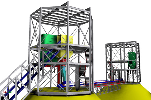
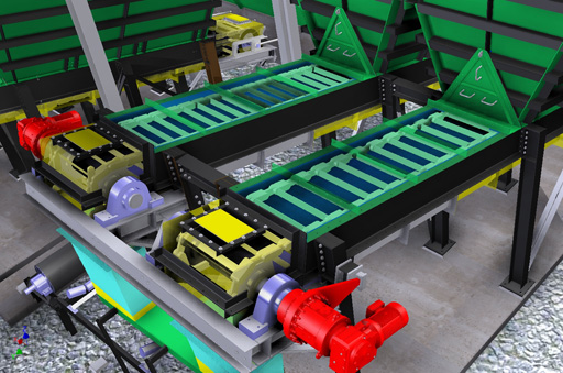
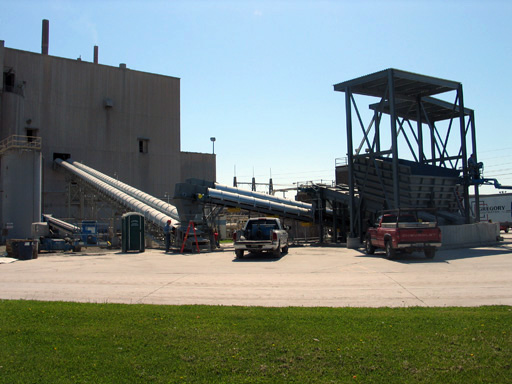
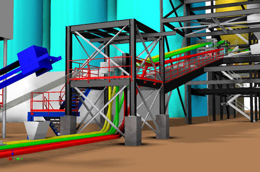
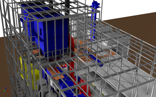
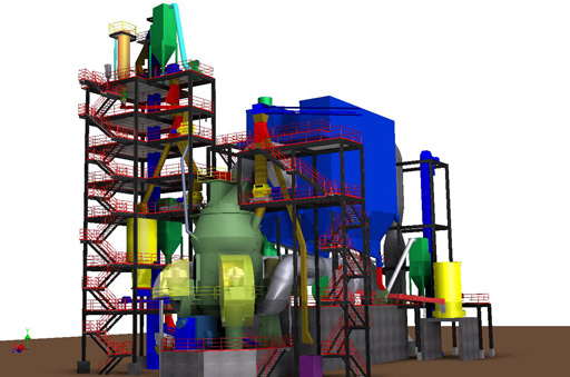
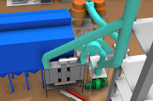
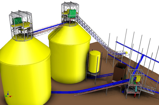
Three-dimensional modeling is our standard for plant design. We use the model to develop general arrangements; structural and electrical plans and elevations; detail, fabrication, and assembly drawings; and drawings for chutes, ducts, and piping. Drawings are typically issued in DWG format.
We also use the model for interference checks, material quantity takeoffs, and collaboration with the project team. This approach helps improve design coordination, reduce errors, and make complex installations easier to visualize.
Model deliverables
Models can be provided in formats such as DWF and 3D PDF. These formats require compatible viewing software; browser PDF viewers may not display interactive 3D content.
Download the sample DWF model or download the sample 3D PDF.
Analysis and construction planning
The 3D model defines the geometry for CFD analysis. Flow rates, temperatures, material properties, and other operating data are specified separately as model inputs and boundary conditions.
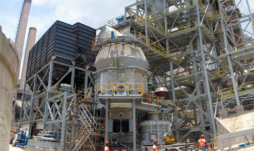
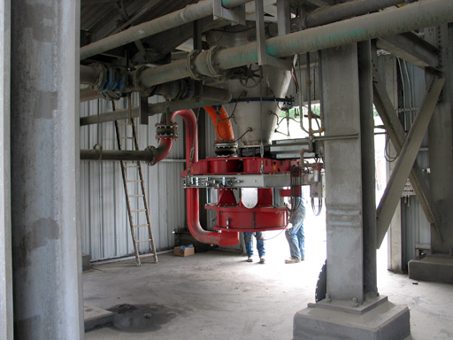
Model-based walkthroughs and construction-sequencing videos help the project team review installation steps and equipment access. For example, a sequence can help verify whether a mill shell section can pass through an existing building without interference with columns, beams, or bracing. Physical prototypes can also support design reviews.